Concrete wall results are presented in the Wall Panel Design spreadsheet on the Concrete tabs, the Concrete Reinforcing spreadsheet on the Concrete Wall tab and the detail reports. Results are reported on a region by region basis.
The Wall Panel Design spreadsheet contains
Note:
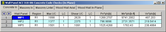
The Concrete In tab provides in plane code checks and capacities relevant to the in plane behavior of the wall.
The
The LC columns report the load combination that produces each of the highest code check values.
The Pn*Phi reports the axial capacity of the wall.
Note:
The Mn*Phi reports the calculated in plane moment capacity for the region.
Note:
The Vn*Phi reports the calculated in plane shear capacity for the region.
The Concrete Wall tab contains reinforcement results for each region in a concrete wall panel.
Note:
![]()
The Concrete Wall tab displays the thickness, horizontal and vertical reinforcement sizes, and spacing for each region in the concrete wall.
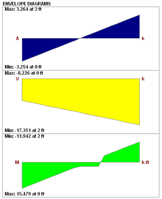
The detail reports show the overall geometry, analysis, and design for the individual regions/stories of the wall panel. The report also shows envelope diagrams for the forces and moments in the region.
Three basic types of detail reports are provided: Wall Summary, Region and Opening.
Once you have a solved model, the detail reports become available. They are accessible in two ways:
 . This will open up the detail report window.
 button on the Selection toolbar. Clicking this button and clicking on a wall panel will open up the detail report window for that wall panel.
Note:
Once the detail report window is open, you will see a dialog area at the top.
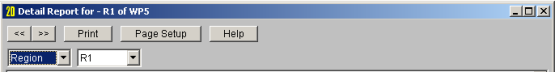
These options control the display of the Detail Report:
 - The arrow buttons allow you to scroll quickly between the different wall panels in your model.
 - This button will allow you to take a snapshot of the current detail report you are viewing so that it can be added to a report. View the Printing topic for more information.
 - The first drop down list allows you to select between individual Region and Opening (Lintel) results and a summary of the entire Wall. Below we will explain the importance of each of these sections.
 - The second drop down list allows you to select between different Regions or Openings within the individual wall panel.
 - If you have selected a Region, then you have the option of whether to view the in plane or out of plane report.
This report gives an overview of the wall, a summary of the controlling code checks and deflection information. This report also displays information about the wall, similar to the Region Input Echo and also gives an image of the wall. The image shows region locations, wall length and story dimensions, and the nodes that define the corners of the wall panel.

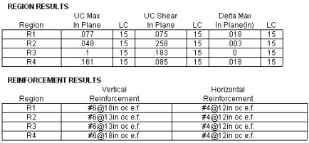
The Region Results section gives the tabulated results of all regions in the wall for in plane design axial/bending, shear and deflection for quick reference. You can view the individual region reports to get a more detailed explanation of these values.
The Reinforcement Results section gives the reinforcement results for each region in the wall.
This window gives information for your wall on a region by region basis. The Region detail report is split into
Note:
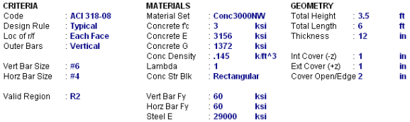
Below is the input echo portion of the detail report.
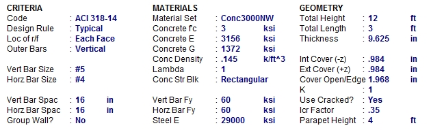
| Criteria | Description |
|---|---|
| Code | Gives the code used to design the wall. |
| Design Rule | Gives the design rule used to design reinforcement and cover for the wall. |
| Loc of r/f | States whether reinforcement is defined at each face of the wall or centered. |
| Outer Bars | States whether the outer bar in the wall is vertical or horizontal. |
| Bar Size |
States the bar size for both horizontal and vertical reinforcement |
| Bar Spacing |
States the bar spacing for both horizontal and vertical reinforcement |
| Group Wall? | States whether the regions in the wall are grouped or not. See the Concrete Wall - Design Rules topic for more information. |
| Materials | Description |
|---|---|
| Material Set |
States the Material used for the design of the wall. |
| Concrete f'c |
States the compressive strength of the concrete. |
| Concrete E |
States the modulus of elasticity of the concrete. |
| Concrete G |
States the shear modulus of the concrete. |
| Conc Density |
States the unit density of concrete used for self-weight calculations. |
| Lambda | States the lightweight concrete factor for shear design. |
| Conc Str Blk | States whether a rectangular (Whitney's) or parabolic stress block was used. |
| Bar Fy | States the reinforcement strength for both vertical and horizontal bars |
| Steel E | States the modulus of elasticity for reinforcement. |
| Geometry | Description |
|---|---|
| Wall Dimensions |
States the height, length, and thickness of the wall panel region. |
| Cover Dimensions |
States the interior, exterior, and edge reinf. cover dimensions. |
| K | States the effective length factor which is used in determining slenderness of the wall. |
| Use Cracked? | States whether a wall is considered to be cracked or not. Defines whether or not to use cracking in the determination of the moment of inertia. |
| Icr Factor | States the factor that Igross is multiplied by to get the cracked moment of inertia. This defaults to 0.7 for in plane and 0.35 for out of plane. |
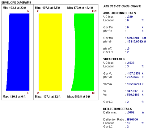
These diagrams show the axial forces
Because the enveloped results displayed are always the maximum values and because axial and bending forces are checked per their combined effects, the forces in the envelope diagrams won't necessarily be the forces that the wall region is designed to. For example, if there is a high bending moment at the top of a wall region and a high axial force at the base of the wall region, the program will do a check at each location up the wall region, considering the shear and moment at that location for THAT load combination. Thus, the maximum axial force given at the location of maximum bending may NOT be the axial force for the LC that produced the maximum bending.
This portion of the report gives the capacity and strength values at the section in the wall region where the combined check is maximum, as well as the governing load combination. Much of this information is also reported in the Concrete Wall Panel Design spreadsheets.
Axial/Bending Details
The axial and bending capacity are based upon an interaction diagram for the wall region. See below for interaction diagram information. The program computes the code check based on making a straight line through the origin, the moment/axial force demand location and where that line crosses the interaction diagram curve.
Shear Details
The shear details section gives the shear demand required in the wall region. The in plane shear strength of the concrete and steel are listed separately, along with the code-prescribed maximum allowed shear. For more information on shear capacity of concrete walls, see the Concrete Wall - Design topic.
Deflections
The deflection listed in the detail report is based on the finite element analysis of plate elements. This deflection agrees well with beam theory, thus can be calculated based on beam equations.
Note:
- If the deflection ratio is larger than L/10000, then L/10000 will be reported.
- If you are checking a hand calculation for in plane deflections, be sure to include the deflection due to shear and consider the cracked moment of inertia.
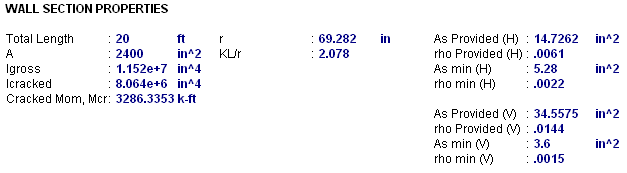
This section reports the properties used to calculate the wall capacities. The reinforcement details (minimums and provided area) are reported.


ACI 318-14 Section 6.6.4.5 (ACI 318-11 Section 10.10.6) considers moment magnification of non-sway frames. This is essentially the P-little delta effect in the form of an amplified moment due to the effects of element curvature, Mc. This moment replaces the actual demand moment in design checks. For more information on this see the Concrete Wall - Design topic.
Note:
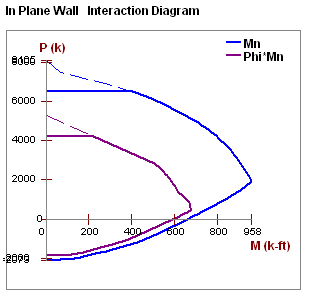
The program uses a concrete solver to create the interaction diagram and uses this diagram to calculate the capacity of each wall region based on the demand axial force and moment. The program then computes the code check based on making a straight line through the origin, the moment/axial force demand location and where that line crosses the interaction diagram curve.

The last section of the detail report consists of a graphic cross-sectional view of the wall. This view gives cover dimensions, reinforcement size and spacing, and the wall thickness for placement verification.
The
Since the lintel is not being designed, much of this information is not used but is displayed for reference.
| Information | Description |
|---|---|
| Valid Region | This is the region that the forces are being considered over. The program will sum forces of the region directly above the opening and the forces given in the detail report come from this portion of the wall. |
| Total Height | This is the height of the region above the opening that forces are being reported for. |
| Total Length | This is the width of the opening that the lintel is spanning. |
| Thickness | This is the thickness of the wall. |
| Other Information |
All of the other information is general information for the overall wall. |
The